Mobile Service Vehicle Diagnostics Shrewsbury Shropshire &Mid-Wales
Supply of engine sensors
Petrol & Diesel Engine Management
Modern vehicles have complex engine management systems designed to
Increase engine efficiency giving higher power output proportional to engine capacity
Give better fuel economy
Reduce air pollution from harmful exhaust gas emissions.
Engine Control Computer
The vehicle engine electronic control module is a computer tasked with control of engine operating parameters and is often linked to other vehicle computer systems to allow exchange of data.
Sensors
The engine control unit compares voltage and resistance values from input sensors to calculate;
Throttle position sensor (TPS) or Accelerator pedal position sensor detects driver request to increase or decrease speed of the engine.
The Brake pedal switch senses when the brake pedal has moved as the driver attempts to slow down the vehicle and stop.
Brake switch signals may be sent to the engine management controller to take the engine off load, decrease power, and also to the anti-lock braking system,
and to body control module to signal operation of brake lights.
Clutch switch detects position of the clutch pedal. Engine controller may respond by reducing engine power as the clutch is disengaged (pedal down).
Crankshaft position sensor (CKP)
Crankshaft position sensor signal is used to detect rotational speed and timing position of the engine crankshaft. The CKP sensor may be used during engine start up to signal
fuelling and ignition is required.
Camshaft position sensor (CMP)
CMP is used to detect which cylinder and part of the engine operating cycle is occurring during engine operation
from intake air temperature sensor,coolant temperature sensor, cylinder head temperature sensor
from Mass air flow sensor (MAF), manifold absolute pressure sensor (MAP or vacuum) , turbocharger boost pressure sensor,
detected from (Lambda or Oxygen sensor) measuring Oxygen content of exhaust gas before catalytic converter.
Monitoring of Exhaust gas recirculation flow , position monitoring of flap or valve.
Engine Fault Codes
The engine control unit of a modern vehicle is capable of condition monitoring of system components. Faults may be logged by the engine management control unit and stored in memory , which can later be read using diagnostic code reading tool. Faults may be indicated to the vehicle driver by MIL engine management light illumination on instrument panel. Unfortunately, fault code logging requires very fast data collection to detect every electronic fault, much beyond the capabilities of most computer systems, so it is quite likely for an intermittent vehicle fault to exist which may have been too fast or brief for detection.
Test and Repair
A scan for fault codes is only the beginning of a repair to identify what the engine management computer detects as a fault by comparison to programmed parameters.
Further testing may involve wiring checks with
Test light
Multimeter
Oscilloscope signal testing
In addition mechanical system checks with vacuum and pressure guages may be reqired
Following testing, a faulty wiring circuit may be repaired or component cleaned or replaced.
Diagnostic Equipment Functions
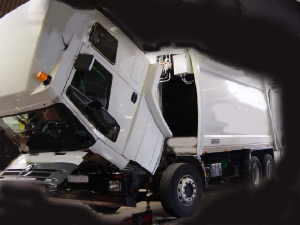
We have vehicle diagnostic equipment capable of testing Car, Van, Commercial HGV vehicle, Construction plant and Tractor Engines
Engine fault diagnostic testing equipment is capable of
Actuator testing is used to verify wiring circuits and component operation by operating suspect component. The actuator test function can allow some components to be thoroughly cleaned which may save replacement cost.
Programming and Coding
Components such as electronic fuel injectors , throttle bodies etc may need coding adaptation to the vehicle ecu .
Advanced system testing
Advanced system testing can be carried out using oscilloscope signal test methods,/p>
Reset Procedures
Following repair work the fault code memory of the vehicle computer will need to be reset to clear stored fault codes.
Common Faults : Sensors and Actuators
Mechanical Position and Speed sensors :
Camshaft position sensor :
Function : Identify cylinder phasing. A faulty cam position sensor may prevent engine starting
Crankshaft (CKP)position sensor
Function : Identification of engine crankshaft position and to allow ecu calculation of engine speed and combustion forces. often AC signal with Frequency and amplitude signal proportional to engine rotational speed.
Typical failure : Signal errors can occur due to failed sensor , phonic wheel damage, or wiring connection faults .

Vehicle speed sensor or VSS
Function: Input to control unit network to sense vehicle speed which may be taken from gearbox sender, axle speed sender,or antilock braking wheel speed sensor. Vehicle speed signal may be used at several modules eg engine control unit, speedometer, tachograph, also for vehicle tracking
Driver Input Sensors
Throttle position sensor (TPS)
Accelerator Position sensor (APP) function: Driver demand signal. TPS failure may occur due to wear of potentiometer track causing driverability issues such as flat spots and hesitation when accelerating.
Brake Pedal Position & Clutch Pedal Position sensors
Function : Stabilise idle speed and fuel delivery quantity when engine is off load . Faults may occur due to worn out switches resulting in false (implausible) signals.
Temperature Sensors
>Intake Air Temperature Sensor
IAT may be incorporated with air mass meter , with MAP sensor (T-MAP) or seperate.
Coolant Temperature Sensor
Function: Engine temperature measurement by engine coolant temperature. May be used to provide signal to control unit to activate cooling fan or adjust fuelling from cold start to warm up. Temperature signal is processed to compensate engine smooth running by control of fuel delivery egr position, & diesel pre heat function.
Flow Sensors
Mass Air Flow (MAF) sensor
Function: Measures volume of air entering engine air intake and combustion chambers.
Air Mass Meter
Function: Measures weight of air entering intake tract. Engine load sensor which can effect fuel metering (petrol engine) or EGR position (diesel engines) . Typical fault code P0100
Exhaust gas recirculation ( EGR )
EGR system functions to reduce combustion temperature and oxides of Nitrogen ( Note : not Nitrous oxide !) EGR and Idle speed control ( ISC ) devices are particularly prone to failure due to build up of carbon and soot deposits which can restrict the air inlet system of the engine. EGR systems may cause the MIL warning lamp to illuminate intermittently and flag a P0400 EOBD fault code due to "critical system malfunction" as described on certain diagnostic equipment !Pressure and Vacuum Sensors
Manifold Absolute Pressure
Function: MAP sensor measures engine load by vacuum (petrol engines) or boost pressure (turbocharged engines) at intake manifold. Split or blocked pipes can effect operation. MAP signal can influence fuel control, EGR, and turbo boost.
Fuel Delivery System
Low and high pressure fuel injection pumps, pressure regulator, fuel injectors. Prone to faults caused by fuel contamination , and general wear.
Boost pressure control :
Turbocharger waste gate position and hence boost pressure control is often actuated by electrical solenoids controlling valves in vacuum circuits.
Boost pressure control Common faults:
Exhaust Emissions Gas Sensor
Lambda Sensor (fitted to Petrol & LPG fuel systems)
Voltage signal to ecu allowing measurement of oxygen content of exhaust gas. Used as a feedback signal to control fuel quantity delivery.
Lambda Sensor Faults: Can deteriorate due to age and contamination causing slow switching or total failure. Lambda sensor fault codes may relate to problems other than the sensor itself.
Lambda sensor operation can be affected by sensor temperature
Lambda sensor feedback signal is only used when engine operating temperature is sufficient to enable closed loop control status.
A second lambda sensor may be fitted in the exhaust system after the catalytic converter to monitor condition of the exhaust catalyst.
Actuators
Fuel injectors
EGR valve
Throttle Motor
Solenoids
Turbocharger wastegate controller

 Autoelectrical Installation
 Air Conditioning Climate Control
 Alternators
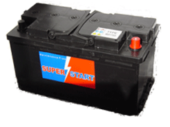
 Batteries
 Starter Motors
 Onboard Power
 HGV Inspection
