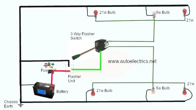


Image shows a basic wiring circuit for vehicle direction indicators consisting of power supply from battery +ve terminal to fuse.
Power from fuse to terminal 49 of indicator flasher relay.
Flasher relay output is from terminal 49a to the 3 way switch.
3 way switch closes circuit to either RH or LH indicator circuit depending on position.
Signal wire from switch output carries power to either RH direction indicator lamps or LH direction indicator lamps.
circuit is completed as current passes through bulb filaments to chassis return to battery -ve.
There are alternative methods for creating a flashing direction indicator circuit using positive earthed supplies.
Another alternative wiring method incorporates use of a body control unit in place of the flasher relay and may be either negative switched or positive switched.
We operate a mobile autoelectrician service around Shrewsbury, Shropshire and Mid-Wales areas UK.
We can supply most parts for your kit car indicator wiring project please enquire by email.
3 Way Indicator Switch Part no. HC180039
Indicator Flasher Relay (see https://www.autoelectrics.net/12v_flasher_relay.html for part numbers)
Fusebox
Fuses
Single core cable
Crimp terminals
Bulbs
Lamp units